Couplers and Connectors - by Natalie Grieve


Couplers and Connectors
Source: http://hw-server.com/fiber-optic-cable-utp-categories
Fibre Optic Splicing
What is fibre optic splicing?
Fibre optic splicing involves joining two fibre optic cables together. The other, more common, method of joining fibres is called termination of connectorization. Fibre splicing typically results in lower light loss and reflection than termination making it the preferred method when the cable runs are too long for a signal length of fibre or when joining two different types of cable together. Splicing is also used to restore fibre optic cables when a buried cable is accidently severed.
There are two methods of fibre optic splicing: fusion and mechanical.
If you are beginning to splice fibre, you might want to look at your long term goals in this field in order to chose which technique best fits your economic and performance objectives.
Mechanical Splicing
Mechanical splices are simply alignment devices, designed to hold the two fibre ends in a precisely aligned position thus enabling light to pass from one fibre into the other.
Typical loss: 0.3dB

Fusion Slicing
In fusion splicing a machine is used to precisely align the two fibre ends then the glass ends are “fused” or “welded” together using some type of heat or electric arc.
This produces a continuous connection between the fibres enabling very low loss light transmission.
Typical loss: 0.1dB

Mechanical vs. Fusion Splicing
Mechanical splicing has a low initial investment ($1000 – $2000) but costs more per splice ($12 – $40 each)
Fusion splicing has a lower cost per splice ($0.50 - $1.50 each) the initial investment is higher ($15000 – $50000 depending on the accuracy of the features of the fusion splicing machine being purchased). The more accurately you need the alignment, the more you pay for the machine.
Fusion Splicing Method
Fusion splicing is a junction of two or more optical fibres that have been permanently affixed by welding them together by an electronic arc.
Four basic steps to fusion splicing:
1. Prepare the fibre – cleanliness is the main concern
2. Cleave the fibre
3. Fuse the fibre
4. Protect the fibre
(Website includes further descriptions of this process)
Source: http://www.pdhengineer.com/courses/ic/IC-3007.pdf
With a fibre optic system the data link transmitter converts an electrical input signal to an optical signal. Then, the optical fibre transmits this optical signal. Finally, the data link receiver converts the optical signal back to an electrical signal identical to the original input.
Optical source launches optical power into a fibre and optical fibres couples light into another fibre. This launching of optical power or coupling of optical power from one component to the next is important.
A system connection may require a fibre optic splice, connector or coupler.
One type of system connection is splicing (permanent connection). A fibre optic splice makes a permanent joint between two fibres or two groups of fibres. There are two types of fibre optic splices: fusion and mechanical.
Another type of connection that allows for system reconfiguration is a fibre optic connector. Fibre optic connectors permit easy coupling and uncoupling of optical fibres.
Fibre optic couplers distribute or combine optical signals between fibres. Couplers can distribute an optical signal from a single fibre into several fibres. Couplers may also combine optical signals from several fibres into one fibre.
Fibre optic connection losses may affect system performance. Poor fibre end preparation and alignment are the main causes of coupling loss.
Optical Fibre Coupling Loss
Ideally, optical signals coupled between fibre optic components are transmitted with no loss of light. However, there is also some type of imperfection present at fibre optic connections that causes some loss of light. It is the amount of optical power lost at fibre optic connections that is a concern of system designers.
The design of fibre optic systems depends on how much light is launched into the optical fibre from an optical source and how much light is coupled between fibre optic components, such as from one fibre to another. The amount of power launched from a source into a fibre depends on the optical properties of both the source and the fibre.
The loss in optical power through a connection is defined similarly to that of signal attenuation through a fibre. Optical loss is also a log relationship.
The loss in optical power through a connection is defined as:
Loss = 10log_10(P_1/P_0)
Where, Loss = optical power loss in the connection, P_1 = the power accepted by the connected power, P_0 = the power emitted from the source fibre in a fibre-to-fibre connection.
Fibre-to-fibre connection loss is affected by intrinsic and extrinsic coupling losses. Intrinsic coupling losses are caused by inherent fibre characteristics and jointing techniques causes extrinsic coupling losses. Fibre-to-fibre connection loss is increased by the following sources of intrinsic and extrinsic coupling loss:
- Reflection loss
- Fibre separation
- Lateral misalignment
- Angular misalignment
- Core and cladding diameter mismatch
- Numerical aperture (NA) mismatch
- Refractive index profile difference
- Poor fibre end preparation
Reflection Losses
When optical fibres are connected, optical power may be reflected back into the source fibre. Light that is reflected back into the source fibre is lost. This reflection loss, called Fresnel reflection, occurs at every fibre interface.
Caused by a step change in the refractive index that occurs at fibre joints – most cases due to ends of each fibre being separated by a small gap (usually air).
This source includes an equation for the reflection if necessary.
Occurs twice in fibre-to-fibre connection: optical power reflected when light first exits the source fibre, and also reflected as optical signal enters the receiving fibre.
Fresnel reflection at each interface must be taken into account when calculating the total fibre-to-fibre coupling loss and may be very significant.
Gels are used to limit these reflection losses.
Fibre Alignment
Thee basic coupling errors that occur during fibre alignment are: fibre separation (longitudinal misalignment), lateral misalignment and angular misalignment.
Mechanical imperfections introduced by fibre jointing techniques
Fibre separation: small gap remains between fibre-end interfaces
Lateral misalignment: two fibres are offset in a perpendicular direction
Angular misalignment: axes of two connected fibres are no longer parallel and intersect at some angle
Lateral and angular misalignment typically has greater coupling loss than fibre separation.
Fibre-end preparation
An optical fibre end face must be flat, smooth and perpendicular to the fibre’s axis to ensure proper fibre connection. Light is reflected or scattered at the connection interface unless the connecting fibre end faces are properly prepared.
Fibre mismatches
Source of intrinsic coupling loss
Intrinsic coupling loss results from differences (mismatches) in the inherent fibre characteristics of the two connecting fibres
Fibre mismatches occur when manufacturers fail to maintain optical of structural tolerances
Include: fibre geometry mismatches, NA mismatch, and refractive index profile difference
Fibre Optic Splices
A fibre optic splice is a permanent fibre joint whose purpose is to establish an optical connection between two individual optical fibres.
System design may require that fibre connections have specific optical properties:
Low loss – met only by fibre-splicing
Mechanical splice: mechanical fixtures and materials perform fibre alignment and connection
Website includes further information on this but I haven’t included it due to the loss that mechanical splicing has.
Fusion splice: localised heat fuses or melts the ends of two optical fibres together
Each splicing technique seeks to optimize splice performance and reduce splice loss.
Fibre splice alignment:
1. Passive alignment: precision reference surfaces (grooves or cylindrical holes)
2. Active alignment: monitoring loss through the splice at alignment, or using a microscope to accurately align the fibre cores for splicing
To monitor loss either an optical source and optical power meter or an optical time domain reflectometer (OTDR) are used.
Active alignment procedures produce low-loss fibre splices.
Fusion Splicing
Using localised heat to melt or fuse the ends of two optical fibres together
Website includes a diagram of the basic fusion splicing apparatus and more on the fusion process
Multi-fibre splicing
Can use fusion to restore connection, but most splicing techniques use mechanical splicing methods (ribbon splice)
Fibre Optic Connectors
Fibre optic connector is a de-mateable device that permits the coupling of optical power between two optical fibres or two groups of fibres.
Fibre optic connectors can introduce modal and reflection noise. Using only single mode fibre with laser sources eliminates this modal noise, or only low coherence sources such as LED with multimode fibre.
Website includes different types of connectors
Fibre optic couplers
Some fibre optic data link requires more than just point-to-point connections.
In many cases these types of systems require fibre optic components that can redistribute (combine or split) optical signals throughout the system.
One type of fibre optic component that allows for the redistribution of optical signals is a fibre optic coupler – device that can distribute the optical signal (power) from one fibre among two or more fibres. It can also combine signals.
Fibre optic couplers attenuate the signal much more than a connector or splice because the input signal is divided among the output ports. For example with a 1 x 2 fibre optic coupler, each output is less than one-half the power of the input signal (over a 3dB loss).
Summary:
Fiber optic connections transfer optical power from one component to another. Fiber optic connections also permit fiber optic systems to be more than just a point-to-point data link.
A fiber optic splice is a permanent joint between two fibers or two groups of fibers.
Fiber optic connectors permit easy coupling and uncoupling of optical fibers.
Fiber optic couplers distribute or combine optical signals between fibers.
Radiance is the amount of optical power emitted by a unit area of emitting surface per unit time in a specified direction. An optical source's radiance, or brightness, is a measure of its optical power launching capability.
Fiber-to-fiber coupling loss is affected by intrinsic and extrinsic coupling losses. Intrinsic coupling losses are caused by inherent fiber characteristics. Jointing techniques causes extrinsic coupling losses.
A fiber pigtail is a short length of optical fiber (usually 1 meter or less) permanently fixed to a fiber optic component, such as an optical source or detector.
Fresnel reflection occurs twice in a fiber-to-fiber connection. A portion of the optical power is reflected when the light first exits the source fiber. Light is then reflected as the optical signal enters the receiving fiber.
Index matching gel eliminates or reduces the step change in the refractive index at the fiber interface, reducing fresnel reflection.
Poor fiber alignment is a main source of coupling loss in fiber-to-fiber connections. The three basic coupling errors that occur during fiber alignment are fiber separation (longitudinal misalignment), lateral misalignment, and angular misalignment.
In fiber separation a small gap remains between fiber-end faces after completing the fiber connection. Lateral, or axial, misalignment is when the axes of the two fibers are offset in a perpendicular direction. Angular misalignment is when the axes of the two fibers are no longer parallel.
Single mode fibers are more sensitive to alignment errors than multimode fibers because of their small core diameters and low numerical apertures.
The mode power distribution (mpd) is the distribution of radiant power among the various modes propagating along the optical fiber.
Poor fiber end preparation is another source of extrinsic coupling loss. An optical fiber end face must be flat, smooth, and perpendicular to the fiber's axis to ensure proper fiber connection.
The score-and-break method is the basic fiber cleaving technique for preparing optical fibers for coupling.
Polishing the fiber ends removes most surface imperfections introduced by the fiber cleaving or cutting process. Fiber polishing involves a step-down approach. The first step is to give the surface of the fiber end a rough polish. The next step involves giving the surface of the fiber end a fine polish.
Fiber mismatches are a source of intrinsic coupling loss. Types of fiber mismatches include fiber geometry mismatches, na mismatch, and refractive index profile difference. Fiber geometry mismatches include core diameter, cladding diameter, core ellipticity, and corecladding concentricity differences.
Core diameter mismatch causes coupling loss only if the launching fiber has a larger core radiusthan the receiving fiber.
Na mismatch causes coupling loss only if the launching fiber has a higher na than the receiving fiber.
A refractive index profile difference causes coupling loss only if the launching fiber has a larger profile parameter than the receiving fiber.
Mechanical and fusion splicing are two broad categories that describe the techniques used for fiber splicing. A mechanical splice is a fiber splice where mechanical fixtures perform fiber alignment and connection. A fusion splice is a fiber splice where localized heat fuses or melts the ends of two lengths of optical fiber together.
In mechanical splicing, mechanical fixtures hold the two optical fibers in alignment for an indefinite period of time without movement. The amount of splice loss is stable over time and unaffected by changes in environmental or mechanical conditions.
Arc fusion involves the discharge of electric current across a gap between two electrodes. By placing the fiber end between the electrodes, the electric discharge melts or fuses the ends of the fibers.
Prefusion involves a short discharge of electric current across the gap between the electrodes. In prefusion the fiber ends are cleaned and rounded to eliminate any surface defects that remain from fiber cleaving.
A fiber optic connector is a demateable device that permits the coupling of optical power between two optical fibers or two groups of fibers.
Fiber alignment in a fiber optic connector is the critical parameter in maintaining total insertion loss below the required level.
Fiber optic connectors can affect system performance by increasing modal and reflection noise. Using only single mode fiber with laser sources and only low coherence sources such as light-emitting diodes with multimode fiber eliminates modal noise. Reflection noise is reduced by index matching gels, physical contact polishes, or antireflection coatings.
Connectors:
1. Metallic system: Wire – Soldering, Lossless, Economical
2. Fibre system: Fibre – Splicing, Loss, Economical
Splicing: Permanent connection of two optical fibres
Two mechanisms of splicing: Fusion & Mechanical
To types of splicing:
1. Midspan: connecting of two cables
2. Pigtail: assembly of a fibre that has been factory installed into a connector in one end, with the other free end for splicing to a cable
The quality of splicing is measured by the insertion and reflection losses caused by the splice.
Couplers and connector losses
A connector loss at any splice stems from the fact that not all light from one fibre is transmitted to another. The loss results from:
1. Mismatch: due to fibre’s mechanical dimensions and numerical aperture. An improvement in splicing technique cannot solve the problem. Also known as intrinsic connection loss.
2. Misalignment: caused by some imperfection in splicing that theoretically can be eliminated. An improvement in splicing technique can solve the problem. Also known as extrinsic connection loss.
Misalignment losses in fibre-to-fibre:

Mismatch losses
Coupling efficiency reduction due to mismatch:
1. Different numerical aperture
2. Different core diameter
3. Elliptical cross sections (rather than circular) with cross section are attached with their major axes unaligned
4. The core is not centred in the cladding and the outside cladding is use as the reference for aligning the joint
5. The distance between the excitation point and the connector (due to unknown distribution of power across the fibre end face)
6. Length of fibre following the junctions
Reasonable loss of 0.1dB for splices
Reasonable loss of reusable connectors with losses less than 1dB
Losses due to lateral misalignment
Assumptions:
1. Uniform power distribution over the fibre core (suitable for multimode step index fibre)
2. The lateral misalignment loss is due only to the non-overlap of transmission and receiving cores


-
- Higher ordered modes are more heavily attenuated than lower modes
- Higher ordered modes contained more power near the core cladding interface
- The power density at the end of a long fibre will be lower at the edge of the core than at points near its centre
- For small axial displacements, only the edges of the transmitting core miss the receiveing fibre but the edge contain less than power than is assumed in
L = -10log_10(η)
L = -10log_10(η)
- The actual loss is less than that predicted by theory

Angular Misalignment

End separation loss for multimode fibre

Axial misalignment is potentially the most serious problem in multimode SI fibre.
Source: http://www.thefoa.org/tech/lossbudg.htm
Multimode connectors will have losses of 0.2-0.5 dB typically. Singlemode connectors, which are factory made and fusion spliced on will have losses of 0.1-0.2 dB. Field terminated singlemode connectors may have losses as high as 0.5-1.0 dB.
References
Basics of couplers and connector losses with a look at the maths:
Another method of connecting rather than splicing – an optical fibre connector:
http://en.wikipedia.org/wiki/Optical_fiber_connector
Actual connectors and their specifications:
Glossary of optical terms:
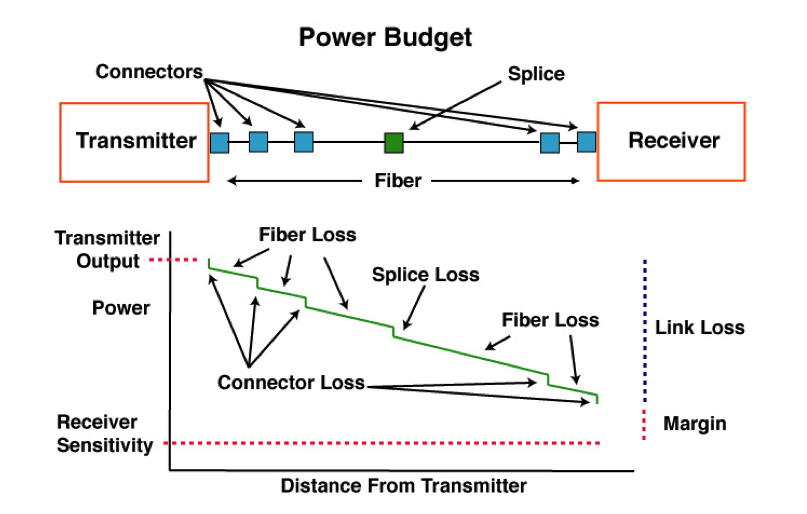
Loss Budget Analysis:
http://www.pdhengineer.com/courses/ic/IC-3007.pdf
No comments:
Post a Comment